Quadcoptor Platform Equations of Motion: Dynamic Model12 min read
Here we’ll derive the equations of motion for copter attitude: it’s roll, pitch, and yaw or orientation in the sky relative to an observer on the ground. The X,Y,Z position of the craft relative to the same observer comprise the other degrees-of freedom.
We’ll later see how thrust and attitude drive to the X,Y,Z position, so we need the attitude equations.
Table of Contents
Degrees-of-Freedom
Our quad operates with 6 degrees-of-freedom (DOF). Its center-of-mass (historical term is center-of-gravity CG so this will be our abbreviation) moves up, down, and sideways relative to an “inertial reference frame”. It also tilts-and-twists as described by three attitude angles below. That term, “Inertial reference frame” just means fixed relative to the environment our object will be moving: not accelerating.
A typical choice of reference frame for a hobby-grade quadcoptor is the, “take-off” point as the zero-point reference, an X-axis pointing north, Y-axis pointing east, and Z-axis pointing down into the earth via the right-hand-rule relative to X and Y axis. Point your right arm north with palm facing east. Curl your fingers towards the east. That is the right-hand-rule from X-to-Y axis. Extend your thumb. It points down. That’s your local, “Z” axis. Let’s call this our North-East-Down (NED) reference frame.
Reference Frame Assumptions
Our craft will operate within sight of this point. We will assume a flat earth. As our quadcoptor moves in the sky the CG position will be determined as an (X,Y,Z) coordinate relative to the inertial reference frame we chose to pin to the ground: this NED frame. Technically, this point on the earth is accelerating as the earth rotates but we’re assuming the entire local flight space is rotating through the day as we all do here on earth, and we accept this as a fair, “inertial frame”.
The quadcoptor is not a simple point mass. If you hold a ball-bearing and move it around you can think of it as a point-mass, and even though you know a bearing twists and rolls ignore that and assume it doesn’t rotate at all. The quadcoptor ball-bearing equivalent places all the mass of the object at the CG for the purposes of the above (X, Y, Z) position relative the the inertial NED reference frame. However, the tilts and rotations of the quadcoptor define the orientation, or attitude of the entire assembly in the sky.
For aircraft there are three angular rotations commonly used to describe orientation:
![]()
![]()
![]()
These give us our remaining 3 degrees-of-freedom, for a total of 6 relative to the earth-fixed NED reference frame:
![]()
The “Body Frame”
Figure 1-2 near the end of the Blakelock Chapter 1 extract below offers a helpful illustration and legend describing the body frame, fixed NED frame, and Euler angles. Here’s the figure. See the PDF below for a detailed description on pages 15 and 16.
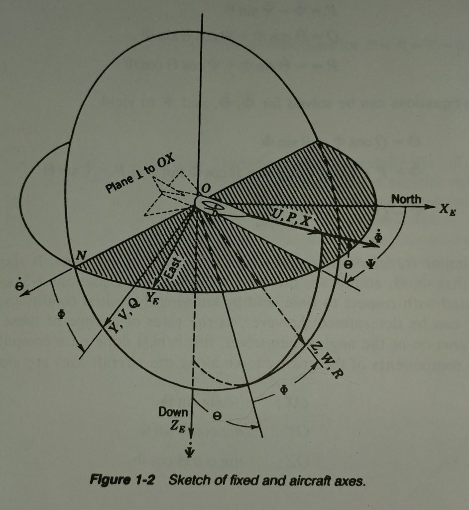
The sketch below illustrates a coordinate system fixed to the body of the quadcopter. The X-Axis is defined to point always from the CG to the location of the first propeller. The Y-axis points towards what I label as the fourth propeller axis, and again, by the right-hand rule, Z is orthogonal to the body X-Y plane by the right-hand rule.
For now, we make a design assumption that our quadcopter will be a square cross configuration and not an “X-wing” form factor. There’s no particular reason other than wanting to sketch it this way and keep the diagrams and coordinate reference frames as simple as possible.
ref_framesAngular Equations of Motion
The Bouabdallah paper refers to the Lagrangian method before summarizing the equations of motion for the 3 rotational axes as described above. I had some difficulty following the author’s use of Euler Angles, and I’m not sure the derivations consistently use these angles within the paper.
Let’s try a Newton-Euler method (Morin p.376) because although the Lagrangian method is elegantly simple, equating the rate-of-change of body momentum to applied forces and torques is straightforward enough.
Recommended Reading
The following text is a “classic.” The first edition was published in 1965, and the second edition was published in 1991. The first 10 pages of the first chapter concisely lay out the equations of motion for aircraft. Blakelock’s labeling and naming of the various body displacements, angles, rates-of-change of position and rotation, linear and rotational momentum, and his description of the Euler angles are helpful.
Retired USAF Colonel Blakelock died in 2015. Click his picture to read his obituary. I am thankful he left behind this great book for us.

It is confusing to think back-and-forth between the “inertial” frame and the “body frame.” Specifically, the rotations on the body that an eventual gyro package will measure as (p,q,r) where…
p = Rotational rate of the body rolling about the body X-axis.
q = Rotational rate of the body pitching about the body Y-axis.
r = Rotational rate of the body yawing (twisting) about the body Z-axis
Then there are “Euler Angles,” representing roll, pitch, and yaw, respectively. These are relative to the fixed frame: the local NED coordinate system in our case.
Blakelock’s first 10 pages offer a clean and clear description that will later lead us to the equations in our main reference for the quadcopter: the Bouabdallah paper.
Blakelock’s straightforward equations-of-motion derivation is included here:
blakelock_eom2Timeout: Angular Momentum Clarification
In a linear system we know the simple statement, “momentum equals mass times velocity”. We know that linear motion in three dimensions means that velocity is a vector with x-, y-, and z-components. Mass for linear momentum is lumped to a point (our ball-bearing example above). It is a scalar. So, in a linear system, we’re left with a momentum vector: the mass times the 3 components of its velocity.
A rotational system in three dimensions will also have a rotational momentum vector, but in this system, “mass” is represented as “moment of inertia (I)” and velocity is the angular velocity of the entire body represented as a three-coordinate vector or (capital or lowercase may vary, but it is almost always this Greek letter,![]() (omega) that is used).
(omega) that is used).
At any instant you can think of this ![]() vector as the axle on which the body spins.
vector as the axle on which the body spins.
To complicate matters further, what was a scalar mass for the linear system becomes not simply a vector of inertia about various axes but a 3×3 matrix!
When we multiply our ‘I’ matrix by our body angular velocity vector, we’ll ultimately arrive at a 3-element vector of angular momentum.
![]()
First let’s get more comfortable with the inertia matrix, ‘I’.
Platform Inertia Matrix
The Blakelock text above skips over the details of the “Inertia Tensor”: a matrix representing the body’s moment of inertia. These are the “I” terms. David Morin provides a good treatment of this topic in Chapter 9 of “Classical Mechanics with Problems and Solutions.” This Chapter is extracted here for your reference. The matrix describing a body’s moment of inertia is covered beginning on P. 376.
MorinCh9Angular Momentum Changes
Page 393 in Morin above states, “Angular momentum, ‘L’ in the body frame changes relative to the fixed frame (our NED frame) by two effects.”
- Body coordinates change relative to the body frame.
- The body frame itself rotates with respect to the fixed frame.
Morin sets ![]() as the momentum vector of the body at any given instant and imagines painting it on the body at this instant. The rate-of-change of momentum with respect to the fixed frame is then…
as the momentum vector of the body at any given instant and imagines painting it on the body at this instant. The rate-of-change of momentum with respect to the fixed frame is then…
![]()
That first term is the rate-of-change of momentum with respect to the body frame. This is what someone sitting on a rigid body would measure:
![]()
The remaining ![]() term is the rate-of-change of the body-fixed momentum vector which is the body momentum at this instant as defined above. The momentum vector in this instant is assumed, “painted” on the body like our body axes. This instantaneously “constant” momentum is rotating with respect to the fixed NED frame on the ground at this instant. This is the
term is the rate-of-change of the body-fixed momentum vector which is the body momentum at this instant as defined above. The momentum vector in this instant is assumed, “painted” on the body like our body axes. This instantaneously “constant” momentum is rotating with respect to the fixed NED frame on the ground at this instant. This is the ![]() .
.
Morin reminds us that the fancy sum above that gives us total change in momentum ![]() is saying just this:
is saying just this:
The total rate of change of angular momentum is the rate of change of momentum relative to the moving frame PLUS the rate of change of the moving frame’s momentum with respect to the fixed frame.
When we have any number of “reference frames” for vectors, this is how we map any vector from one frame to another. There is nothing magic or new here, even though the nomenclature looks fancy.
Body-Fixed Momentum Vector Relative to NED Frame
Just as Blakelock on page 13, Morin p. 394 gives us,
![]()
In Morin chapter 9, you can see the derivation of the “Inertia tensor,” but it simplifies to a diagonal matrix when we select the body-frame axis to be the principal axes of the body.

Blakelock doesn’t zero the lower-left and upper-right terms of the inertial matrix. For a fixed-wing aircraft he maintains a cross-coupling of the inertia terms associated with roll and yaw. If you study his figure 1-2 in the book section above you can make sense of this for an aircraft that does not appear symmetrical front-to-back. However, our quadcoptor is symmetrical here too. Our inertia matrix simplifies to the diagonal matrix above.
This leaves us with ![]() for each body axis x, y, and z. The cross-product
for each body axis x, y, and z. The cross-product ![]() can be computed via the determinant of the matrix below. The determinant of a 3-by-3 matrix can be had by augmenting it with the first two columns as shown and subtracting left-diagonal products from right-diagonal products.
can be computed via the determinant of the matrix below. The determinant of a 3-by-3 matrix can be had by augmenting it with the first two columns as shown and subtracting left-diagonal products from right-diagonal products.

Below are the hand calculations for the ![]() cross-product. The black lines represent the, “right diagonal” products. the red lines represent the left-diagonal products.
cross-product. The black lines represent the, “right diagonal” products. the red lines represent the left-diagonal products.
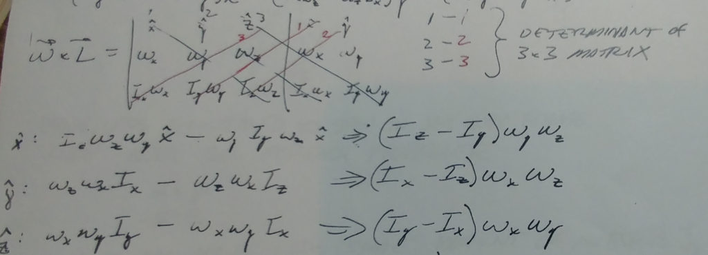
These hand calculations agree with Blakelock equations 1-32 (the central term with the principal axes moments of inertia in parenthesis). Our rotational rates match Blakelock’s as follows:

These are the body rates-of-rotation about the principal axes of the body: the frame, “painted” on the body. We will soon get into details for an Inertial measurement unit (IMU) with gyros that will give us (p,q,r) data for our attitude controller.
Rate-of-change of body momentum relative to the body frame: 
This is what we would measure if we were sitting still on the body.
As in Blakelock’s equation 1-32, we will assume the primary-axis inertia terms are constant. For aircraft, missiles, and the like, fuel burn changes mass and the distribution of this mass within the body. Our battery-powered quad will not experience these changes, but it is worthwhile to consider this effect should we desire to deliver a payload with our quadrotor. When we drop the load, the mass and moments would change.
Blakelock indicates that even when this is relevant for fuel-thirsty aircraft, the above assumption works over time intervals much longer than our tens-of-Hz platform control loop. We would implement a “sliding” controller or “gain scheduling” system that effectively remodels our design periodically as fuel is consumed or payload is released. Between those slower updates, we would take our moment-of-intertia, “I” terms as constants.
Thus, we have
![]()
Combining this with the result above our equations of rotational motion become…

If you assume no applied Torques T (natural rotational response of the system) you can rearrange the above equations to match the Bouabdallah paper equation (6). Note that the “I” subtractions are reversed because, assuming zero applied torque, we move terms to the other side of the equal sign and solve for the angular acceleration.
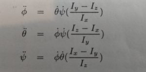
These match when we relate Bouabdallah’s terms to our terms above as follows…

Equations of Linear Motion
The Bouabdallah paper describes a test stand for which various control strategies are studied. The test stand pins the CG to a point, constraining it to angular motion only. The paper does not cover details of linear motion.
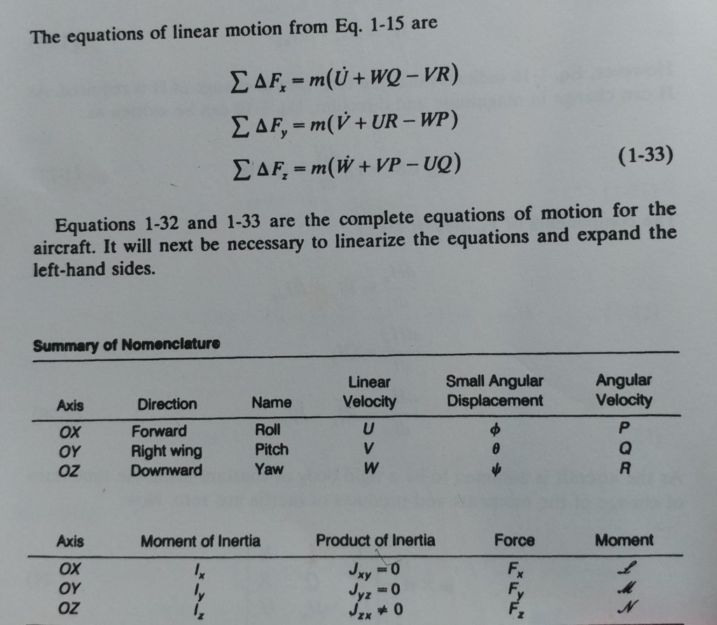
Blakelock’s Chapter 1 above offers good descriptions for modeling linear motion. Below is his conclusion. If you look back at Equation 1.15, you can see how each primary axis velocity couples into the acceleration of the other axes via another cross-product. I’m going to leave this here for now because depending on how we measure position and velocity relative to the body and/or fixed NED frame, these terms may or may not be relevant in our design.
Conclusion
It looks like we have a good handle on the equations of motion now. We have nomenclature and methods for thinking within the two reference frames:
- The North-East-Down (NED) frame is pinned to the earth at our take-off point.
- The Body frame we can think of is permanently painted along the primary (x, y, z) axes of our quadcopter.
In the next post, we’ll discuss the applied torque and force elements of the equations of motion, which are the following terms in the equations above.
![]()
They are the torques and forces that will act on the quadcopter. They will include the desired outputs from the propulsion units, and we can also model external factors such as wind. We will need a controller design that is robust to some applied, “disturbances” from wind, for example.
