Step 2: Retooling for New Controller Design2 min read
Observing incomplete code around the LVDT and poor results tuning the existing scheme, the effort transitions to a redesign. We might still employ the existing PLC, or we’ll evolve a new stand-alone controller for the edge control function.
Regardless, the resident Allen-Bradley Programmable Logic Controller (PLC) is not convenient for system analysis and design candidate iteration. The resident PLC is also responsible for other system functions. As we iterate on a design for the edge position controller, we don’t want to upset the production system. PC-based tooling is used to characterize the system and to evaluate candidate designs before committing to a production-grade form factor, existing PLC or otherwise.
Analysis And Prototype Controller Tooling
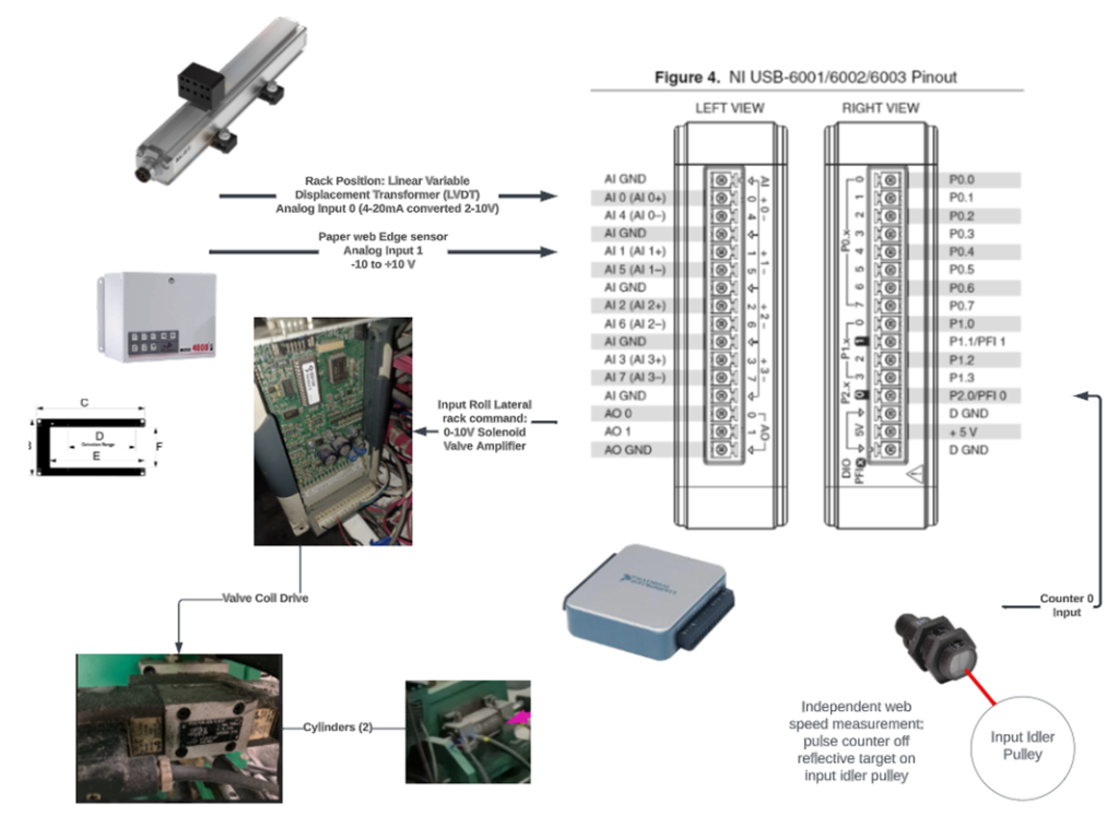
A National Instruments USB-6001 under Laptop (PC) software control provides signal input-output and software control flexibility. This setup aids analysis and candidate design evaluation before committing to a production form-factor and coding environment.

The NI USB-6001 meets our needs for the following…
- -10 to +10 volt output from Edge Guide system
- zero-volts output when edge detected at sensor midpoint
- zero to +10 Volts from the center point to 1/8 inch towards the open end of the ‘C’.
- Saturated +10 V output beyond and when no material within the sensor.
- Zero to -10V from the center point to 1/8 towards the closed end of the ‘C’.
- Saturated -10 V output from 1/8 inch to the closed end of the ‘C’
- Zero to +10 volt LVDT output
- The resident LVDT is 4-20mA but converts to 2-10V with a 500-ohm resistor.
- Zero to +10 volt output to Wandfluh hydraulic solenoid valve amplifier.
- The Wandfluh amplifier maps 0-5 Volts and 5-10 volts to west-east directional drive, respectively.
- The amplifier manages the 24V valve solenoid coil drive to produce the proportional valve behavior.

