Step 4: Controller Structure
The goal is to be suitably responsive and stable in regulating the web edge to the null point of the ultrasonic sensor given the mechanics, drive system, and the sensors provided. We’re not starting with a specification on output roll side-face (0.030 inches for example) and designing a new machine. We’ll analyze the given equipment, implement a suitable controller, and assess the result.
The specification is largely cosmetic: how do the output rolls look compared to customer expectations based on output rolls from similar equipment with edge position control? How it looks to a customer is the loose specification. Some tens-of-thousands variation is assumed adequate based on an assessment of “Acceptable” rolls off similar equipment.
Feedback Scheme
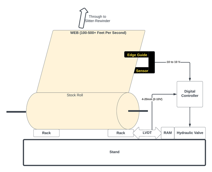
We have two position sensors to work with: the ultrasonic web position sensor and the input rack LVDT position sensor. The web edge moves laterally in response to slide motion. Web position change relative to input rack motion is time-delayed. The edge must travel from the roll tangent point to the ultrasonic sensor location. Slide position is measurable using the LVDT. The slide-induced lateral edge movement sums with Edge variation within the roll and lateral disturbances caused by the output winder pulling the web through the machine.
This sensor configuration is like a motor position controller with a tachometer on the shaft in addition to a shaft position sensor (if we differentiate the LVDT sensor signal). Given the tight coupling of the edge position to the slide position albeit with transport lag, the web position from the ultrasonic sensor is taken as feedback for the position state with a numerically differentiated LVDT output as the velocity state. We are combining the web and the rack into a single two-state feedback control scheme.
Rationale for the two-state feedback scheme
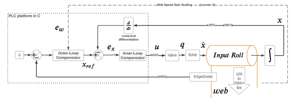
The diagram below illustrates how regulating the position (zero edge sensor output volts) as an outer loop around an inner, differentiated input rack LVDT loop amounts to servo-controlling the speed of the rack slide, not slide position directly.
For relatively large web edge error we ask for considerable rack speed to close the error. As the Edge Guide output approaches zero we ask for slower rack speed. This intuition aids in appreciating the block diagram. The “Compensator” blocks indicate where we will code our controller gains (our subset of PID implementation for each loop). The dotted-line web speed feedback is shown feeding the outer-loop compensator. Web speed feedback facilitates gain scaling to mitigate transport lag.