Step 8: Production Platform Against A Plant Simulator
The controller form factor installs on a DIN rail in a cabinet. Design iteration and debugging against the live system is not practical. To simulate the entire assembly from analog and counter inputs, through C-code to command output we again use the National Instruments USB-6001 as shows here.
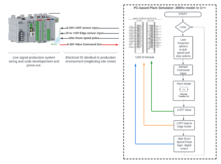
In this configuration, the code behind the USB-6001 is a digital model of the plant. Plant simulator code on the PC hosting the USB-6001 samples our production control unit command output on an analog input to the USB-6001.
The command is processed through a digital model of our identified plant. The sample interval is 5ms (200Hz). The LVDT and Edge Guide sensors are modelled to drive USB-6001 outputs which feed the sensor inputs on our production platform controller.
A digital output simulates the idler drum speed pulse into the production controller’s counter module. User key presses permit speed changes and step inputs for transient response confirmation.
This method permits real signal simulation to facilitate production platform design iteration, debug,ging and scenario testing on a bench with an oscilloscope before production environment acceptance testing.
Comparing Model Performance to Production Code Against the Simulator
Production controller performance against the PC-simulator compares to a model under an equivalent reference input step change. Recall the PC simulator interfaces to the production PLC through the production Analog and digital IO. The PC implements the plant model. I reads the production platform servo valve command as an analog input to the NI-USB module. The simulator runs the command voltage through a plant model filter simulated in C++. It outputs modelled LVDT and Edge Sensor voltages
The intent is to minimize production floor design refinement by iterating against the PC simulator on the bench.
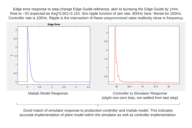
Below is the Simulink model used to simulate an edge step response.
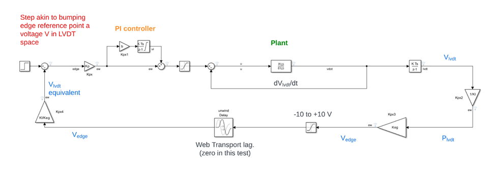
An equivalent step change into the PC simulator is implemented via user keypress. The PLC production code responds to the step. The comparison plot below indicates a match between Simulink model and PC-simulation. The ripple on the controller-to-simulator plot is a product of the relative sampling rates. Transport lag is disabled for this comparison check.